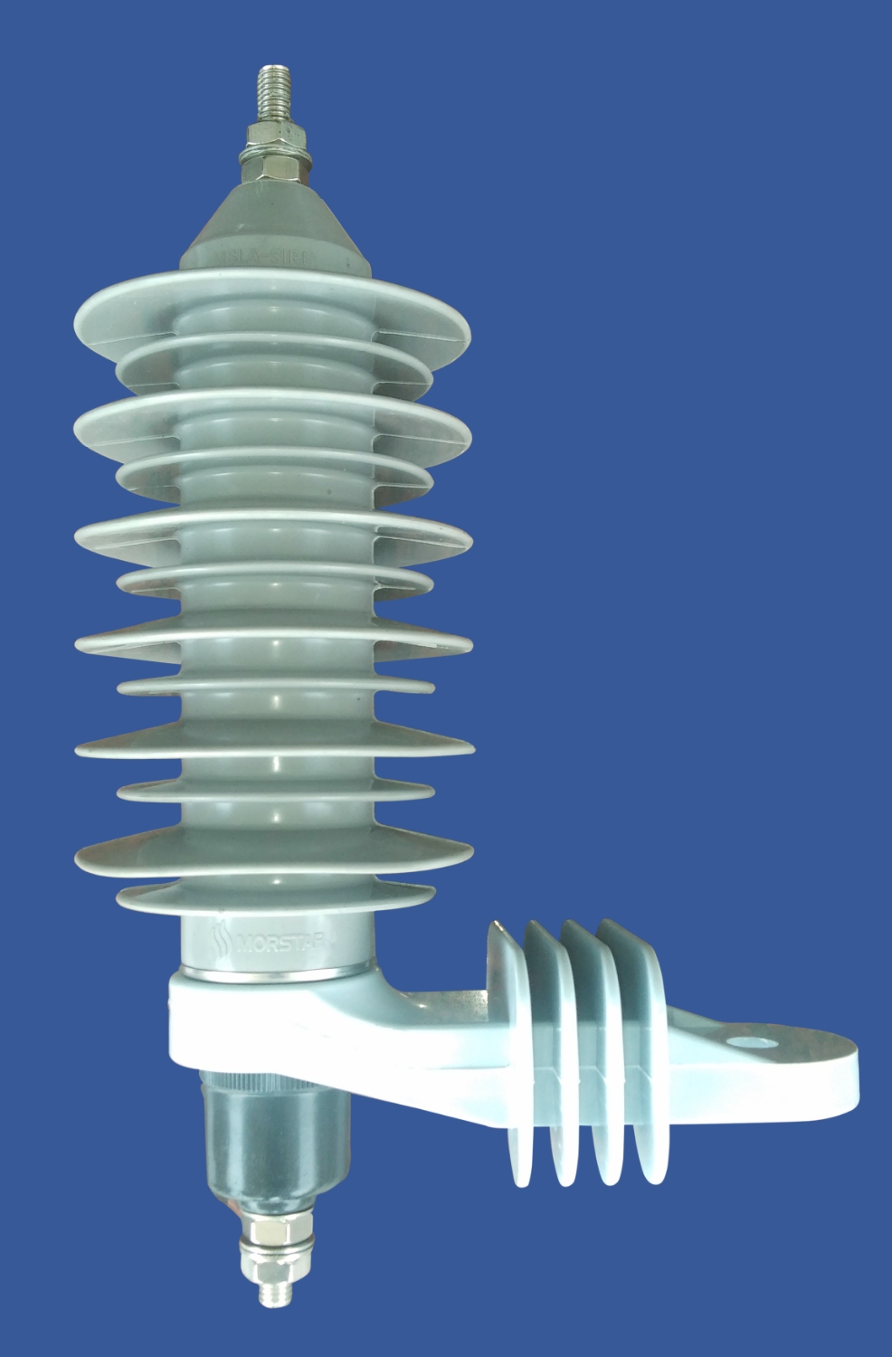
The Surge Arresters type MSLA were designed to operate in distribution systems, in tensions from 3 to 36 kV. It was specially designed to protect transformers, capacitors bank, primary stations, lines, extensions, against power surges in medium voltage distribution systems. The Metal Oxide Varistors (MOV) are enclosed by a cage made of an ECR fiberglass core, providing a rigid structure, ensuring high mechanical resistance. The silicone rubber housing, resistant to UV radiation and weather conditions in general is vulcanized directly on to the Metal Oxide Varistors (MOV) blocks, the ECR fiberglass core and aluminum terminals, fully incorporating the Componentes without leaving voids or gaps, providing an excellent system seal. It was equipped with automatic disconnector whose performance curve coordinates the operation with 12k fuse links.
Description
Features:
- Morstar arresters have mold-on polymer housing for the ultimate seal against moisture ingress
- High strength Fiberglass for high fault-withstand design
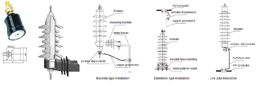
Integrated Ground Lead Disconnet for fast, reliable operation. Operates in less than 2 seconds at 5 amps and less than 2 cycles at 1,000 amps. As a special supporting product for arrester, the disconnector is series connected with arrester. When the arrester comes across any fault, it would operate quickly and let the failed arrester disconnect from the power grid, meanwhile, it would give obvious disconnection symbol, so that the maintenance personnel would find the point of failure and change the arrester in time. On the other hand, when the arrester works normally, disconnector does not work and is under low impedance state, it would not affect the protective characteristics of arrester. The arresters that have been equipped with disconnectors really realize safe operation, maintenance free, convenient and reliable performance.It is popular to use disconnectors for distribution type, power station type and line type arresters in power grid in Japan, occident countries and other developed countries and districts.The disconnectors produced by out company adopt the latest thermal-explosion design, with advantages of fast response and misoperation free, can be equipped with arresters of various models of 3kV above, having the same operating conditions with that of arresters.
Typical Ampere-Second Characteristic Parameters Of Disconnector
| Current (A) | 800 | 200 | 20 | 5 | 0.5 | 0.05 |
| Operation times (S) | 0.01~0.02 | 0.02~0.05 | 0.1~0.2 | 0.5~1.0 | 20~50 | 200~500 |
Continuous Voltage
A preliminary selection that is based on selecting an arrester having a “Continuous Operating Voltage”, or Uc, that equals or exceeds the normal system maximum line-to-earth operating voltage is made. Reference IEC 60099-5.
Power-Frequency Overvoltages
The second application criterion to be met is a condition established by the effectiveness of system grounding. During a single line-to-earth fault, under maximum system voltage conditions, the arrester selected should have a “Rating” (Ur) that will not be exceeded by the voltages on the unfaulted phases at the point of arrester application. One must pay particular attention to systems having low coefficients of grounding, ungrounded systems and systems that are resonant grounded or that may become ungrounded under abnormal conditions of operation. This second voltage consideration may be modified for various system conditions as long as the application does not violate the selected arrester’s “Temporary Overvoltage Capability (TOV)” .Temporary system conditions resulting in sinusoidal power-frequency voltages that exceed arrester “Continuous Operating Voltage, (Uc)” or even “Arrester Rating, (Ur)” can be allowed. Consider the permissible magnitude and duration of these overvoltages (including the full time of system back-up protection), with appropriate allowances for any recent arrester discharge energies.The voltage withstand capability application on ungrounded systems is 1.035 per unit of COV (Uc) for 24 hours. Systems which permit earth faults to remain undetected or operate with one phase earthed for periods in excess of 24 hours will require the use of an arrester having aUc (continuous capability) equal to the system maximum phase-to-phase voltage.
Under some special system conditions, such as transformer energization using certain types of connections and ferroresonance, higher voltages can be experienced by the arrester. To ensure that the arrester’s capabilities will not be exceeded, the resources of systems application engineers are available to make recommendations.
Performance:
There are two series for The designs are tested in accordance with the latest ANSI/IEEE standards for metal oxide arresters.
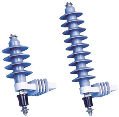
| series MSLA-10 | series MSLA-05 | |
| 01` | High Currect – Sort Duration 100kA | High Currect – Sort Duration 65kA |
| 02 | Low Current – Lon Duration 250 amps | Low Current – Lon Duration 150 amps |
| 03 | Nominal discharge class per IEC 10kA | Nominal discharge class per IEC 5kA |
| 04 | Duty Cycle – 10kA | Duty Cycle – 10kA |
| 05 | Line Discharge Class per IEC: Class 1 | Line Discharge Class per IEC: Class 1 |
| 06 | Minimum Energy Capability – 100% production tests: 2.7kJ/kV |
Minimum Energy Capability – 100% production tests: 2.7kJ/kV |
| 07 | Fault Withstand Capability: 20kA | Fault Withstand Capability: 20kA rms-sym |
| 08 | REA Listed | REA Listed |
Technical specification:Surge Arresters 5 kA and 10 kA for MV Systems to 36 kV


